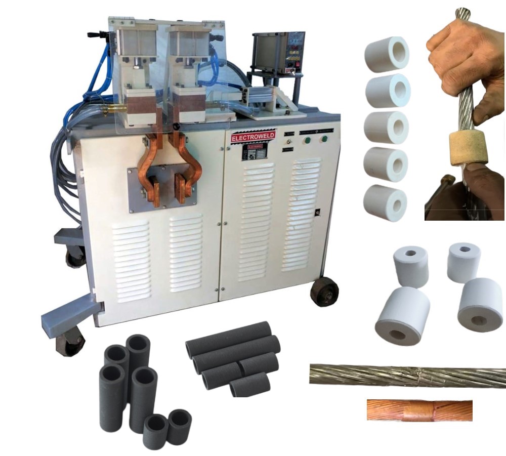
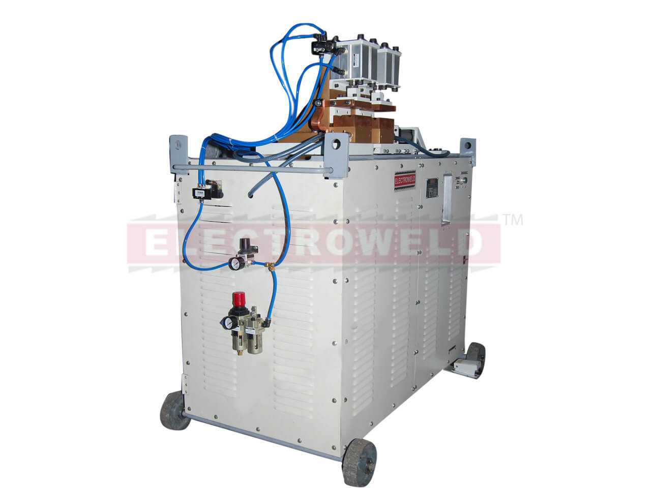
Electroweld industries is a leading manufacturer of resistance welding equipment, serving the industry for over 45 years. Our welding machines are designed to provide a production solution at an affordable price while ensuring reliability and low cost maintenance.
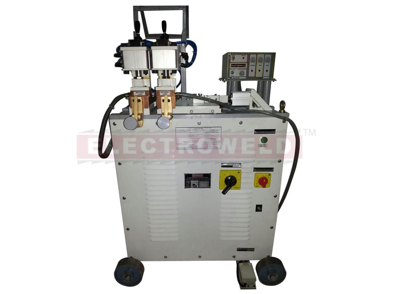
Electroweld Pneumatic Stranded or Bunched Conductor Welder 200KVA (SC-RBW-200PN)
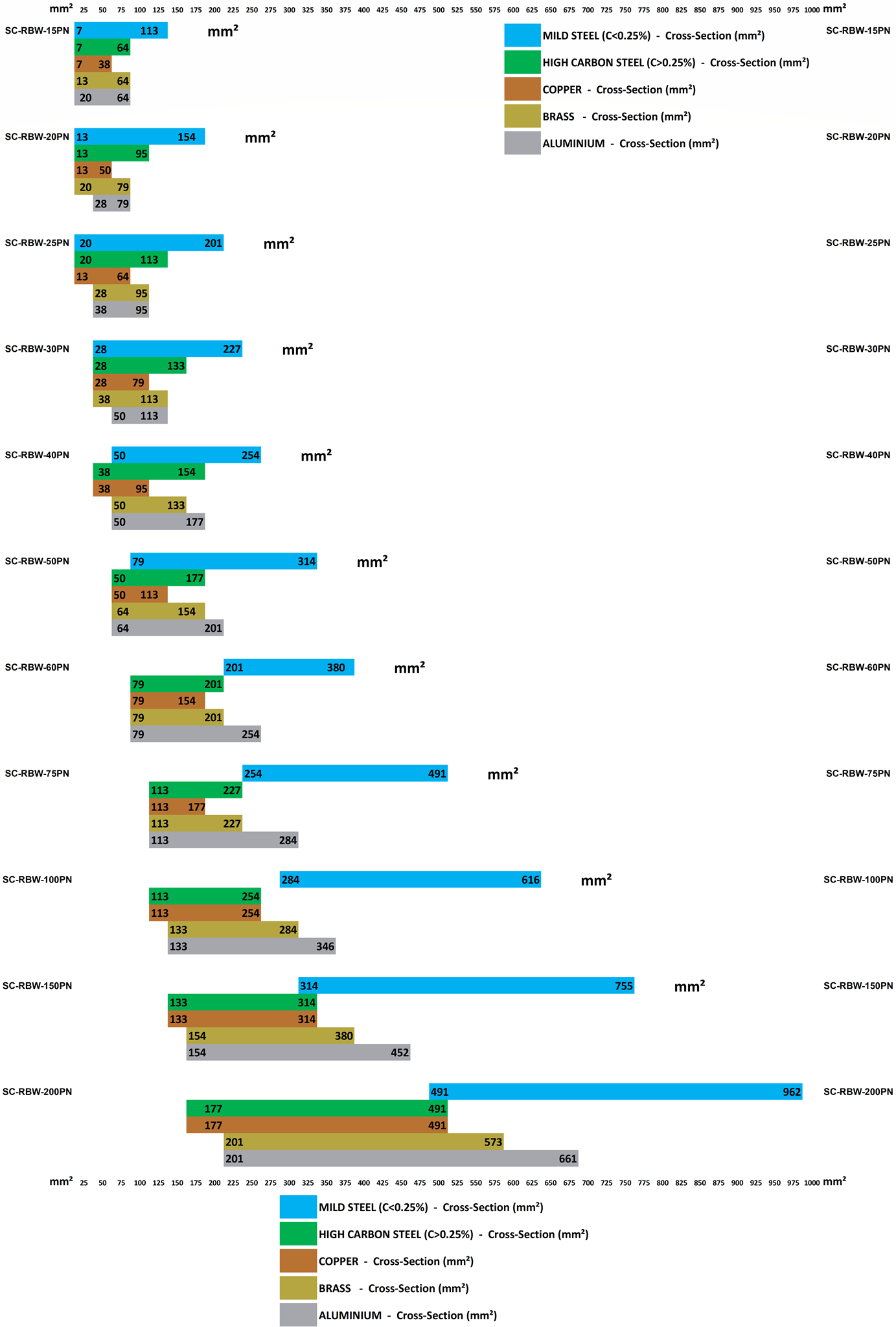
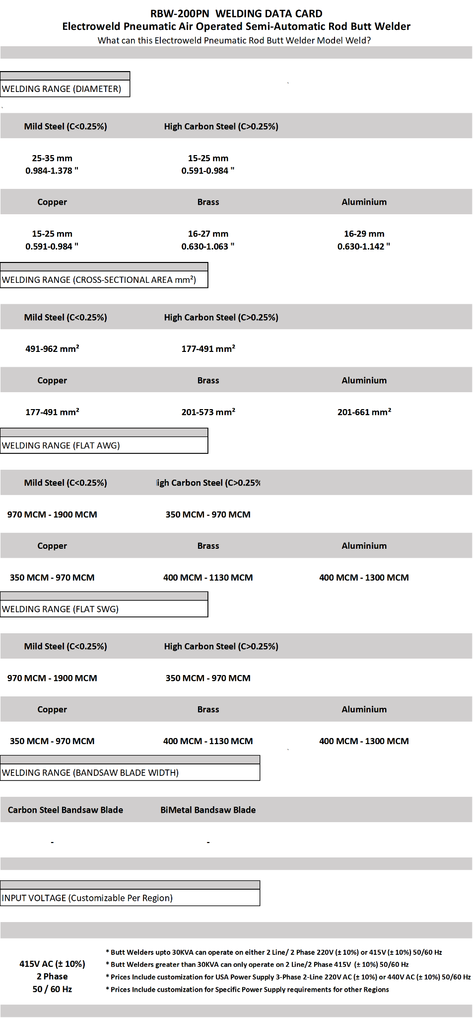
Weldability - Cross-Sectional Area - Mild Steel: 491-962 mm², High Carbon Steel: 177-491 mm², Copper: 177-491 mm², Brass: 201-573 mm², Aluminium: 201-661 mm².
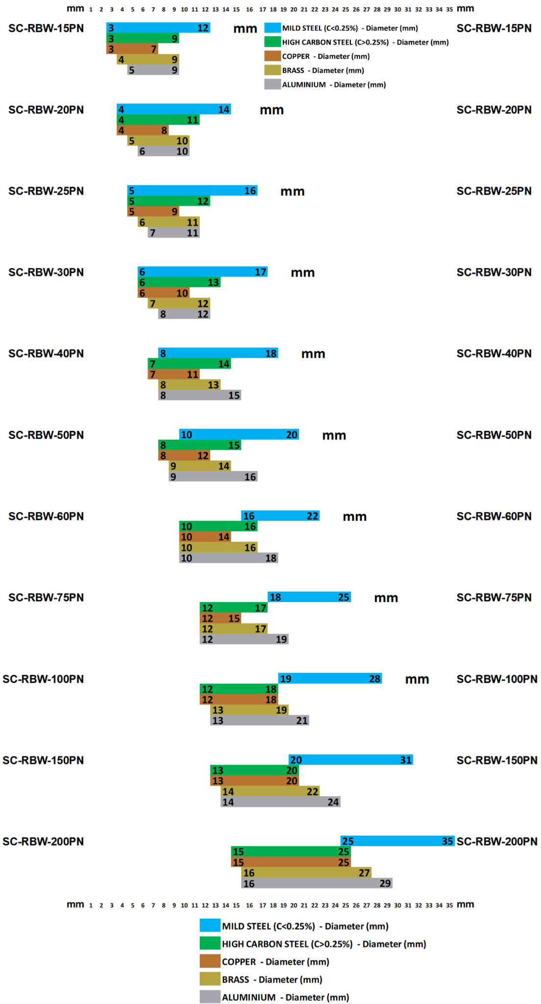
Weldability - Diameter - Mild Steel: 25mm-35mm, High Carbon Steel: 15mm-25mm, Copper: 15mm-25mm, Brass: 16mm-27mm, Aluminium: 16mm-29mm.
Weldability - Welding Range - Mild Steel: 970 - 1900 MCM, High Carbon Steel: 350 - 970 MCM, Copper: 350 - 970 MCM, Brass: 400 - 1130 MCM, Aluminium: 400 - 1300 MCM.
Weldability - Mild Steel: 25mm-35mm, High Carbon Steel: 15mm-25mm, Copper: 15mm-25mm, Brass: 16mm-27mm, Aluminium: 16mm-29mm.
Applications: Upset butt welding of all profiles of wires and flats of iron, steel, alloy and carbon steel, copper, aluminium, brass and other light metals and their alloys. Carbon Steel and Bimetal Blades Butt Welding
Users: Include wire strip and rod drawing mills, transformer motor and switch gear manufacturers, bandsaw and hacksaw blade users, small tool makers for welding mild steel shanks to alloy steel portion of taps, drills, bits, screw drivers, chisels, etc., hoop and ring manufacturers, wire forming industries, cable industries, automobile industries, air-conditioner and refrigerator makers, office equipment makers, etc.
Construction: The machines are constructed with a sturdy light alloy housing and designed as portable models mounted on a moveable chassis fitted with four wheels. They are constructed for quick, easy, and fool-proof operation, the welding process being automatic. Settings are simple, finely adjustable, and reproducible for all variables. Uniform welds of high strength capable of withstanding subsequent drawing ensured.
The Machine has 2 welding Jaws with grooves for welding different sized rods. The clamping action of the welding jaws is controlled via the Left and Right Clamping Levers which in turn activate the Pneumatic Clamping cylinders. The machine is also designed with a Horizontal welding cylinder for providing horizontal pressure on the welding jaws during the welding process.
Simple Settings:
1. ELECTRODE SPACING: Adjust lever on indexing plate depending on the diameter of the rod being welded.
2. WELDING CURRENT: Operate knob of the 8 step switch, current making and breaking is automatic via a built-in electromagnetic contactor.
3. UPSETTING PRESSURE: Micrometrically adjustable with pressure control knob for the incoming compressed air line supplying air pressure to the Pneumatic Cylinders.
4. CURRENT ON / OFF: Weld Initiation via Push Button/ Foot Operated Switch and welding duration electronically controlled via timer values.
TIMER AND % HEAT SETTINGS FOR PROGRAMMING THE AUTOMATIC WELDING CYCLE
Following is the sequence of timers which trigger sequentially once the butt welding process is initiated via the pushbutton or foot operated switch:
(A) 'Squeeze 1' Timer (Setting range on 0-100 scale: 0-2 seconds): Timer for initiating clamping of the job via the 2 Vertical Clamping Pneumatic Cylinders. The clamps engage once the timer expires
(B) 'Weld 2' Timer (Setting range on 0-100 scale: 0-120 seconds or 0-360 seconds-depending on machine): Timer for setting the weld cycle time for the duration of the current applied to the weld job. This timer is sequentially triggered once the Vertical Clamping cylinders have clamped the welding job after the 'Squeeze 1' timer expiry. Additionally the initialization of this timer also triggers the activation of the Horizontal Pneumatic Cylinder which provides Upset Pressure for Butt Welding. On expiry of this timer the welding current is stopped.
(C) 'Forge 1' Timer (Setting range on 0-100 scale: 0-2 seconds): Timer for releasing the clamping of the job via the 2 Vertical Clamping Pneumatic Cylinders. This timer is triggered in sequence once the 'Weld 2' timer expires and this timer disengages the 2 Vertical Pneumatic Clamping Cylinders on 'Forge 1' timer expiry.
(D) 'Forge 2' Timer (Setting range on 0-100 scale: 0-2 seconds): Timer for releasing the upset pressure the job via the Horizontal Upset Pressure Pneumatic Cylinder. This timer is triggered in sequence once the 'Forge 1' timer expires and disengages the Horizontal Upset Pressure Pneumatic Cylinder on 'Forge 2' timer expiry.
Following setting controls the % of welding current applied to the job during the welding process when 'Weld 2' timer is engaged:
(E) % Heat Setting (Setting range on 0-100 scale: 0-100%): Weld Power setting adjusted depending on Diameter of Rod being welded.
Welding Process:
The Machine is provided with a toggle switch to alternate between Welding and Annealing functionality. The actual Welding or Annealing is is initiated with a common push button switch.
1. Fix the above simple settings, clamp the job end-to-end in the center of the welding jaws.
2. Press the welding push button and the welding then takes place automatically. Unclamp Job.
3. To anneal, put spacing lever to max. position. Clamp Job centrally in the Pneumatically Clamped Welding Jaws or the provided Annealing Jaws. Press the annealing push button till annealing temperature is reached.
Design Features:
UPSET TRAVEL: Movable platen travel on parallel guides.
UPSET PRESSURE: Provided by the Horizontal Pneumatic Cylinder and adjustable with a knob controlling the incoming air pressure.
CLAMPS: Lever operated adjustable 'floating' steel clamps of precision quick acting design ensure firm preset clamping pressure. Release is quick and easy. Foot operated switch operation also supported for clamping operation if required.
ELECTRODES: Special wear resistant copper alloy electrodes provided with precision 'V' grooves, permit rapid and accurate alignment of wires/rods/cables/blades..
WELDING CURRENT ADJUSTMENT: By means of a 8 step rotary switch from 50% to 100%.
ELECTRODE SPACING: Obtained with ease by a lever set against an indexing plate, adjusting in 10 steps.
WELD CURRENT INITIATION: By pressing welding / annealing push button after clamping the job to weld position simply starts the automatic welding cycle. Foot operated switch operation also supported for weld initiation operation if required.
ELECTRONIC CONTROLS:
(A) Thyristorised synchronous electronic sequence timer consisting of: Squeeze, weld, forge, Weld/No-Weld and heat control unit range 1-99 c/s. This is a standard controller offering.
(B) Solid State - three timers provided for squeeze, weld and forge timings - short range 5 - 50 cycles - long range 1 - 10 seconds (50 to 500 cycles). This is a standard controller offering.
(C) Optional Electroweld AY-01 Digital Timer with capability to store upto 25 different weld schedules. This option will replace the standard controller at an additional cost.
(D) Optional Forwel AK-54V Constant Current Digital Controller with capability to store and recall upto 15 different weld schedules (additional cost). This option will replace the standard controller at an additional cost.
CURRENT CUT OFF: Adjustable over a wide range by means of micrometric thimble the setting of which is read on a graduated scale.
ANNEALING FACILITY: Annealing on same welding jaw setup for Low Carbon Steel Rods. For High Carbon Steel, Copper, Brass and Aluminum annealing can be done using the annealing electrodes with screw type clamps provided for ease and quick annealing of the welded job ensuring a flexible zone at both ends of the weld.
PORTABILITY: The machine is mounted on a four wheeled chassis for easy portability.
* Power Requirement is 220V AC 50/60Hz or 415V AC 50/60Hz depending on machine KVA rating
* Prices Include customization for USA 3-Phase 2-Line 220V AC (± 10%) or 440V AC (± 10%) 50/60 Hz
* Prices Include customization for Specific Power Supply requirements for other Regions
* Butt Welders up-to 30KVA can operate on either 2 Line/ 2 Phase 220V (± 10%) or 415V (± 10%) 50/60 Hz
* Butt Welders greater than 30KVA can only operate on 2 Line/2 Phase 415V (± 10%) 50/60 Hz
****Additional set of spares and consumables can be quoted to be added to the shipment as required
Specifications Table:
Weldability - Cross-Sectional Area of the Stranded Cable, Wire or Rope (mm²):
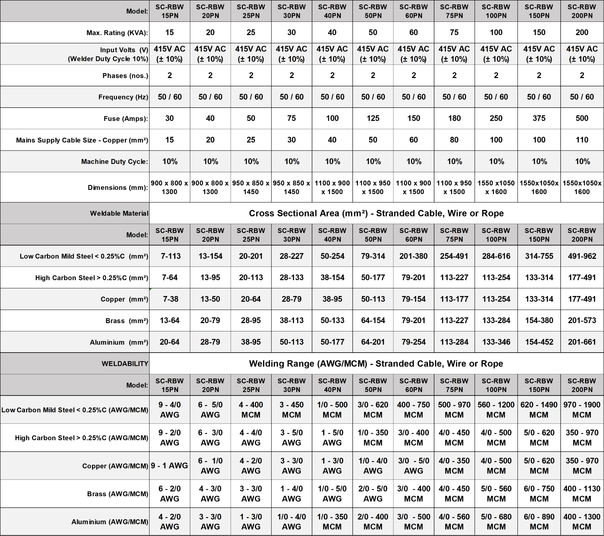
***Duty Cycle can be higher upto 50% with water cooling active on Welding Jaws and the transformer secondary coils.
Product Finder - Cross-Sectional Area of the Stranded Cable, Wire or Rope (mm²):
Weldability - Diameter of the Stranded Cable, Wire or Rope (mm):
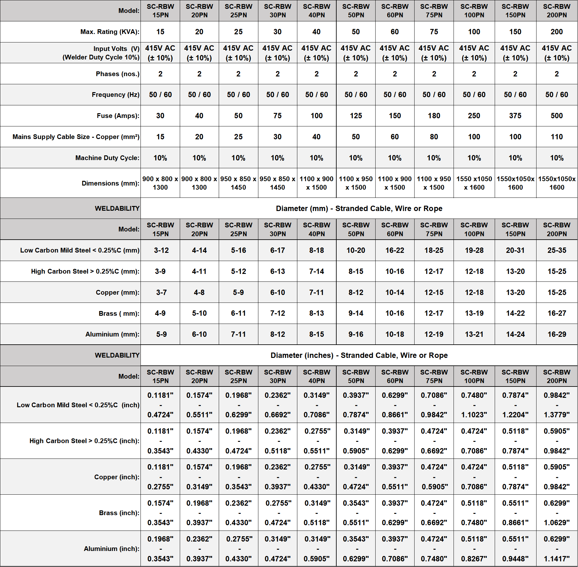
***Duty Cycle can be higher upto 50% with water cooling active on Welding Jaws and the transformer secondary coils.
Product Finder - Diameter of the Stranded Cable, Wire or Rope - (mm):
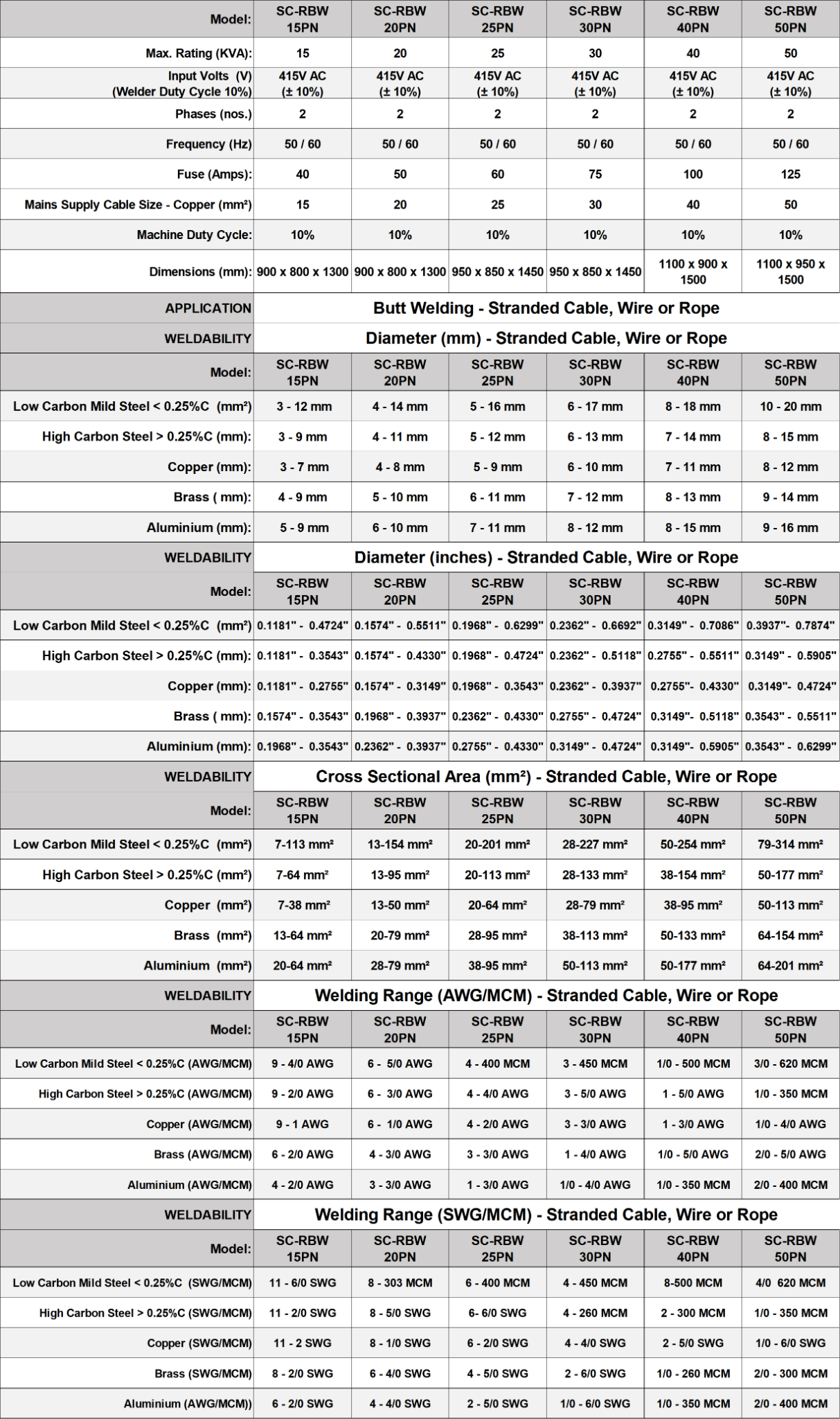
Expanded Specifications Table (Part1):
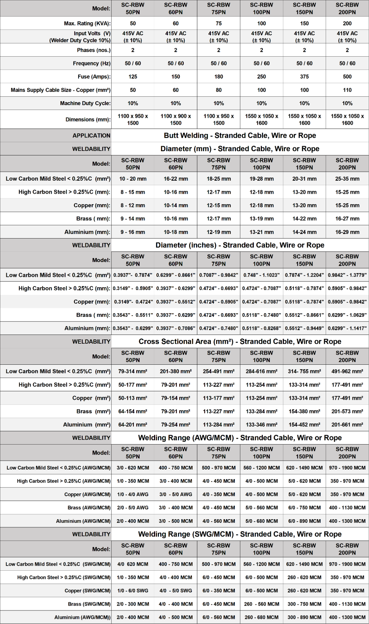
Expanded Specifications Table (Part2):
Optional Functionality
***Weldability - Flat Metal - All Electroweld Wire and Rod Butt Welders can weld Flat Metal jobs when customized with a flat jaw assembly instead of the standard jaws with grooves for wires and rods. For weldability ranges please contact us with the material and cross-section surface area.
****Weldability - Stranded Cables/Ropes/Cords Butt Welding using Glass Sleeves, Ceramic Sleeves or Carbon Sleeves which function as crucibles during the Stranded Cable Butt Welding Application- For weldability ranges please contact us with the material and cross-section surface area.
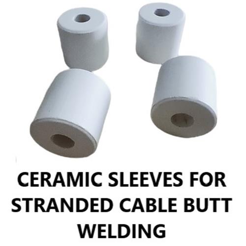
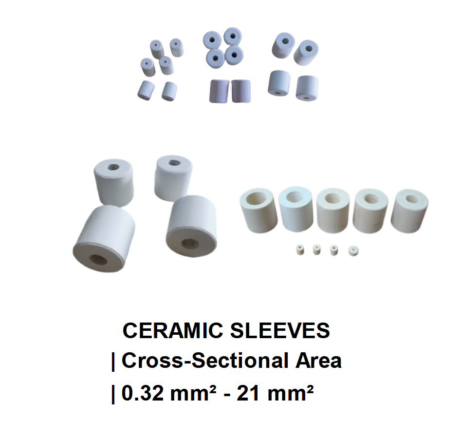
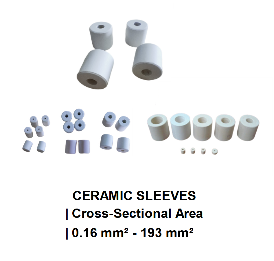
Electroweld Ceramic Sleeves for Stranded Cable Cross Section : 0.16 mm² - 193 mm²
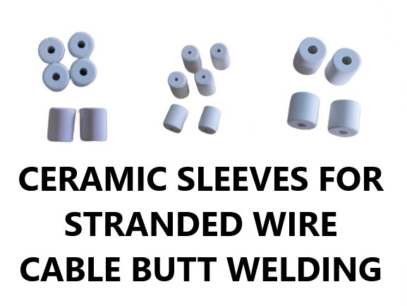
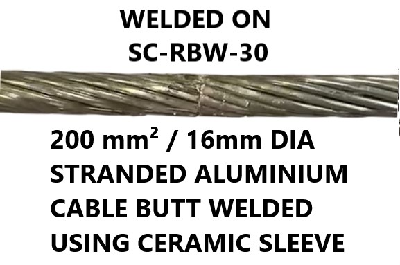
Applications: Electroweld Ceramic Sleeves are designed for butt welding of stranded conductors. Example: For enabling continuous wire drawing manufacturing operations, the two ends of the stranded conductor to be welded are inserted into the Ceramic Sleeve openings on each end, such that they meet in the middle of the tube. This assembly of the stranded cables and ceramic sleeve is then clamped into the jaws of the matching Electroweld Butt Welding machine. When the butt welding process is initiated, the ceramic sleeve act as a crucible and the ends of the stranded conductors inside the sleeve fuse to form a burr free and pore free weld. The ceramic sleeve is then broken with a hammer or mallet revealing the butt welded stranded cable which can then be processed upstream, ensuring continuous operations of the wire drawing manufacturing process.
Note: The Welding Jaw Clamping mechanism on Electroweld Butt Welding Machines is either Hand Operated, Foot Operated or Pneumatic Cylinder Operated, depending on the stranded conductor being welded and the corresponding matching machine rating. Regarding Upset Pressure mechanism in Electroweld Butt Welding Machines- For smaller cross-section stranded conductors, the butt welding upset pressure is applied via spring tension and for larger cross-section stranded conductors, the butt welding upset pressure is applied via pneumatic cylinders. Additionally the clamping pressure should be approximately twice the upset butt welding pressure to avoid slippage and turning of the stranded conductors inside the sleeve during butt welding.
Unique Characteristics of Ceramic Sleeves for Butt Welding Application:
1. Very high compressive strength.
2. Moderate to extremely high mechanical strength.
3. Moderate thermal conductivity
4. High thermal shock resistance.
5. High thermal Stability and operating temperatures.
6. Low co-efficient of thermal expansion.
7. Electrical insulation.
8. Easily and readily machinable.
9. High Hardness, High wear and Friction resistance.
10. Corrosion resistance even at high temperatures.
11. Low Specific Weight.
Ordering and Lead Times for Delivery :
Note: MINIMUM ORDER QUANTITY (MOQ) FOR CERAMIC SLEEVES IN ANY PARTICULAR DIMENSION- 1000 Qty.
Minimum 4-5 Weeks Lead time for Delivery of MOQ. Samples could be made available earlier on request.
Please contact sales@electroweld.com for sample requests, price quotes or purchase orders for your required applications and quantities
Series 1: Specifications Table and Guide for Matching Various Ceramic Sleeve Sizes to Specific Stranded Conductor Cross-Sections for Butt Welding Application :
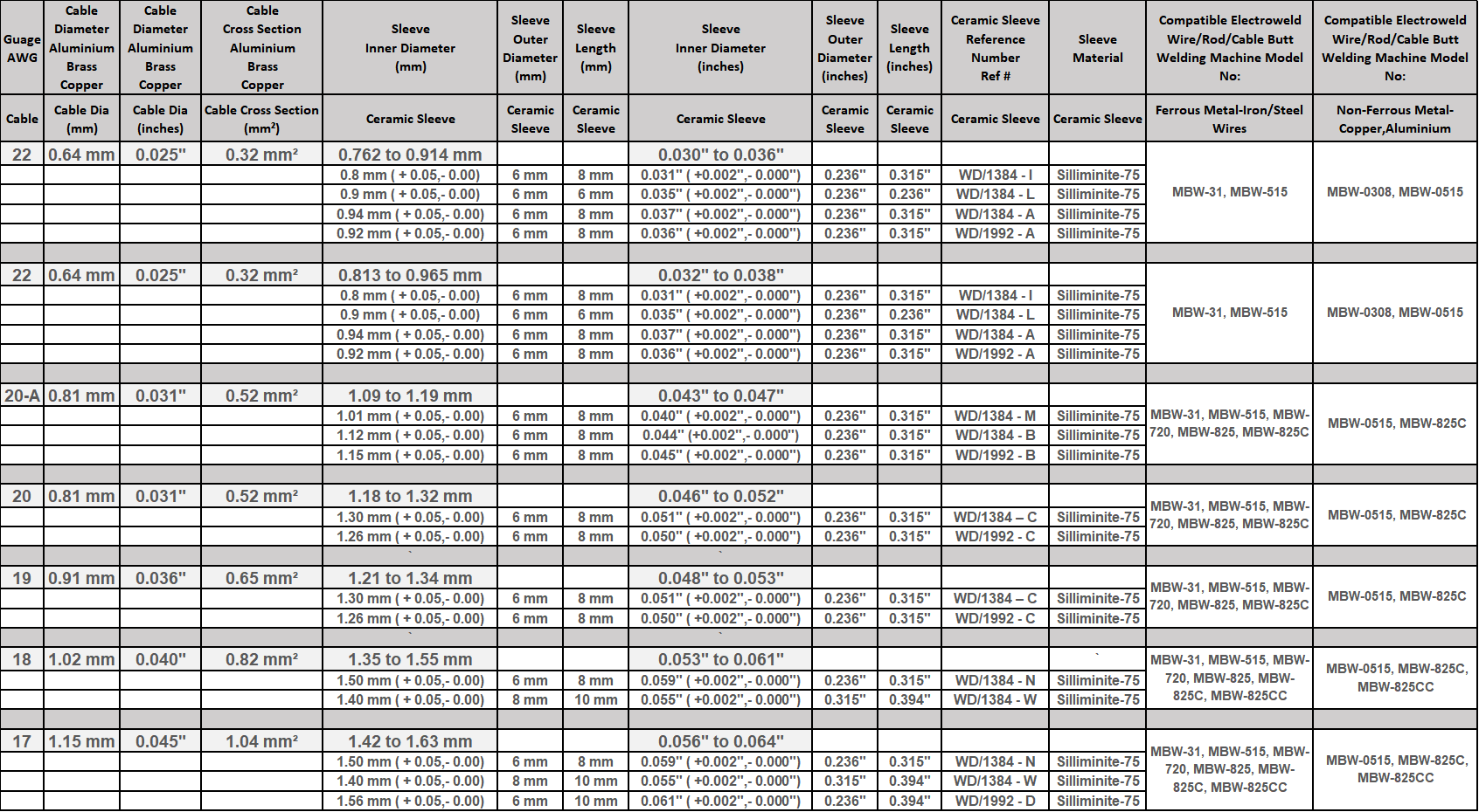
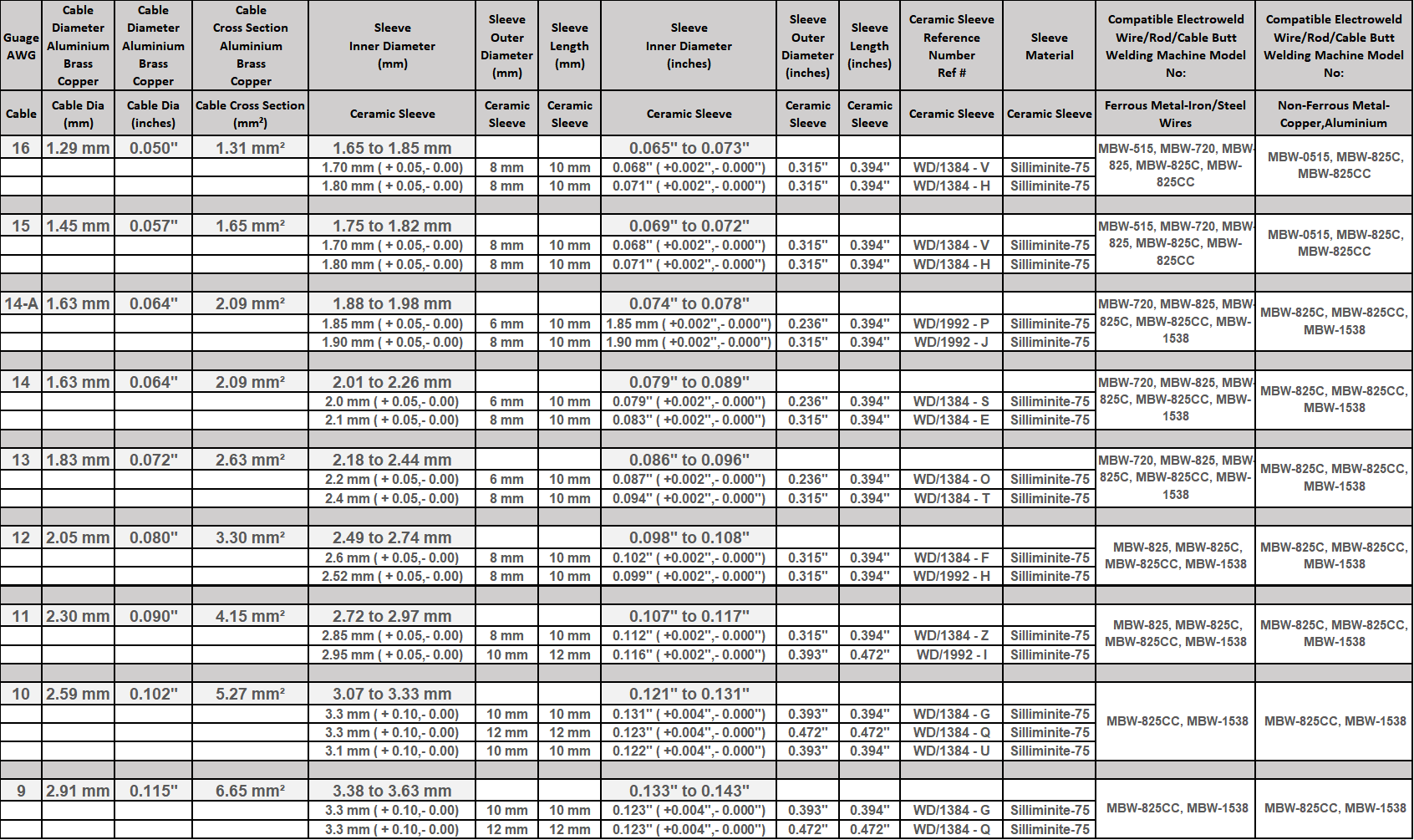

Series 2-Specifications Table and Guide for Matching Various Ceramic Sleeve Sizes to Specific Stranded Conductor Cross-Sections for Butt Welding Application :
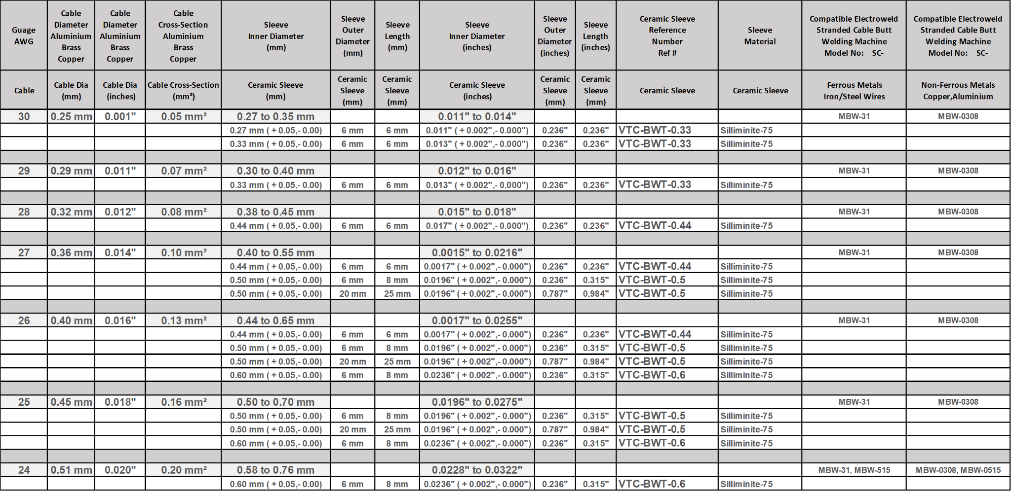
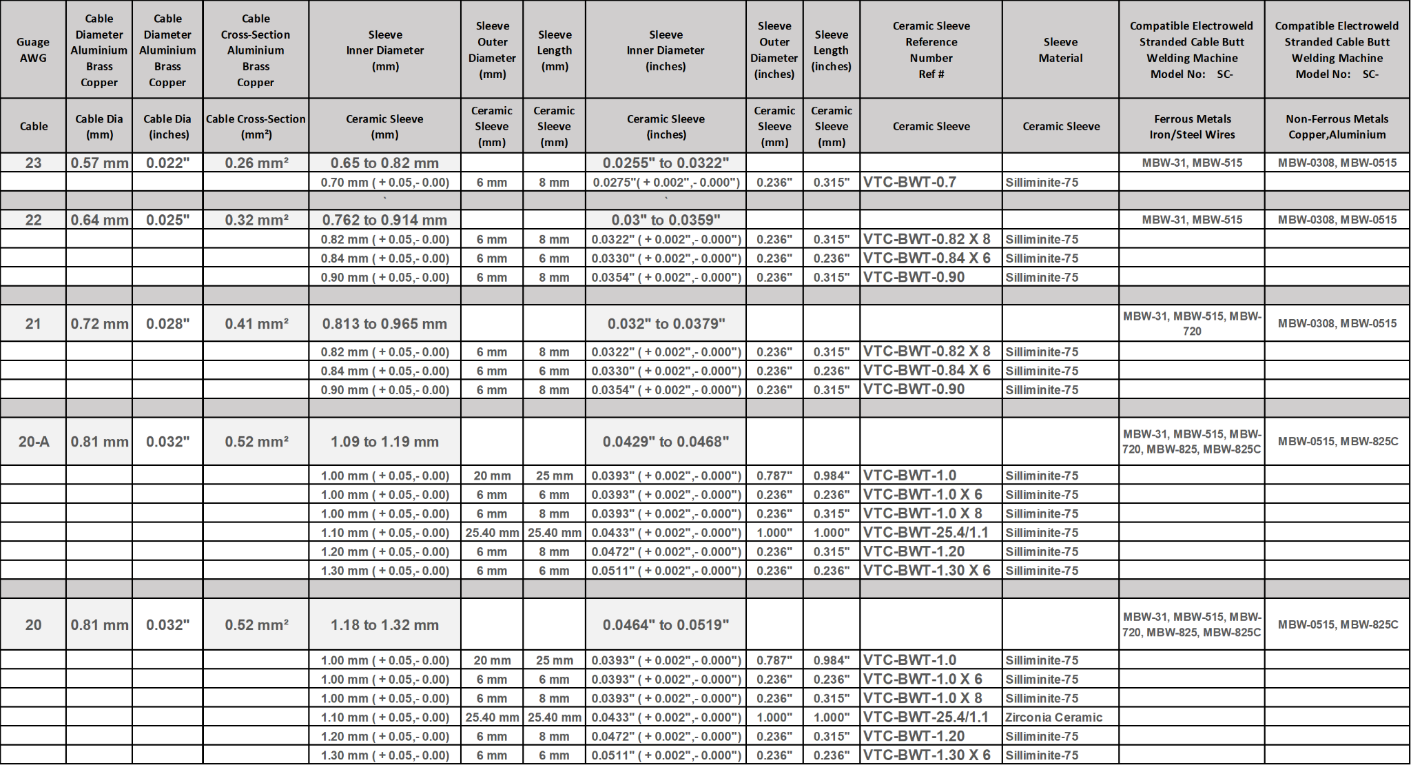
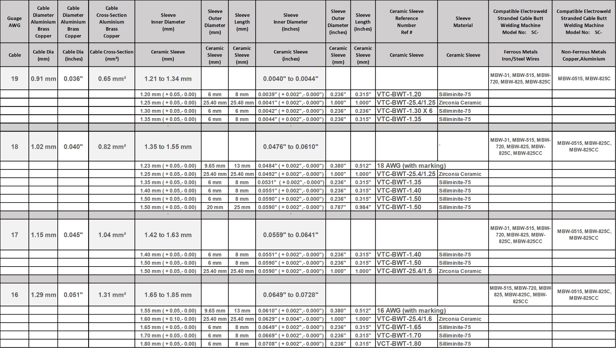
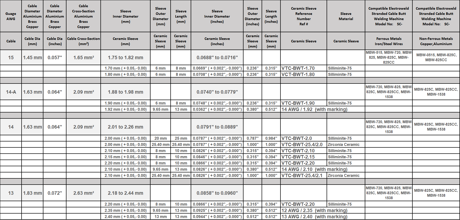
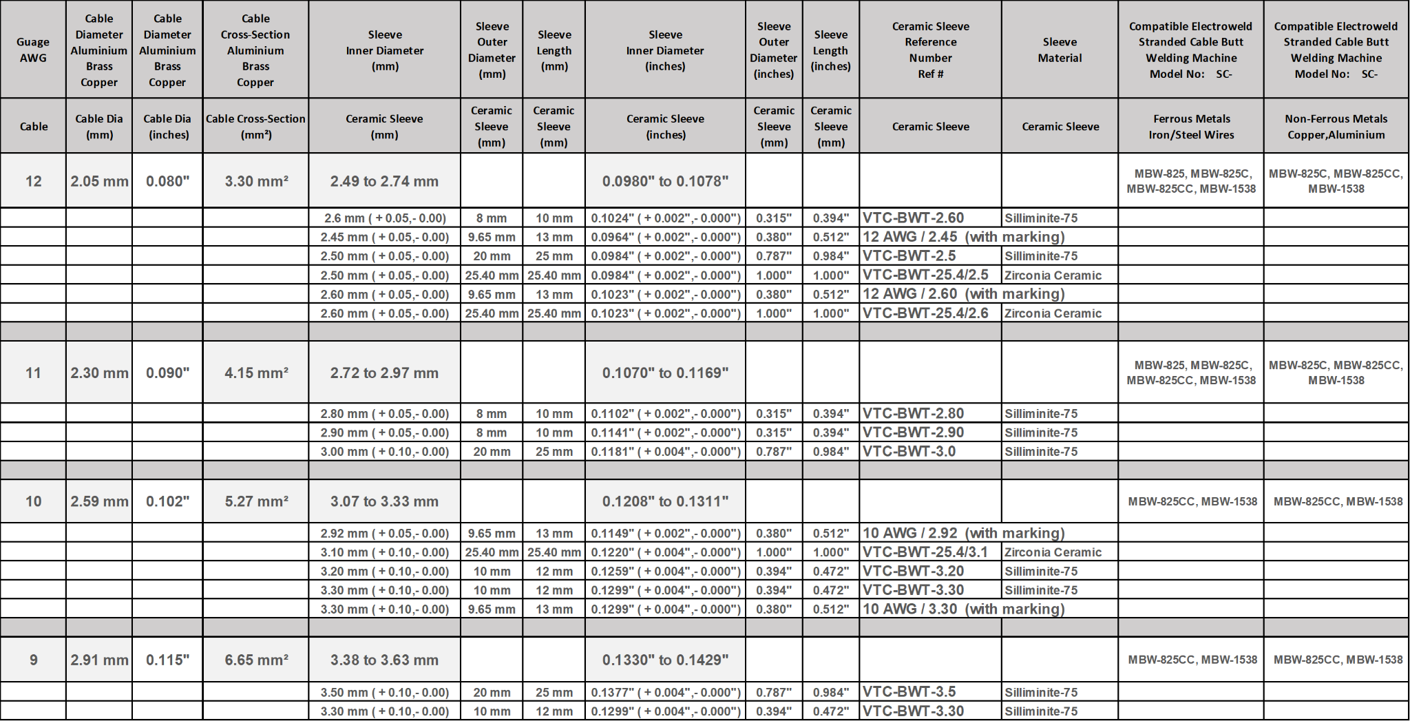
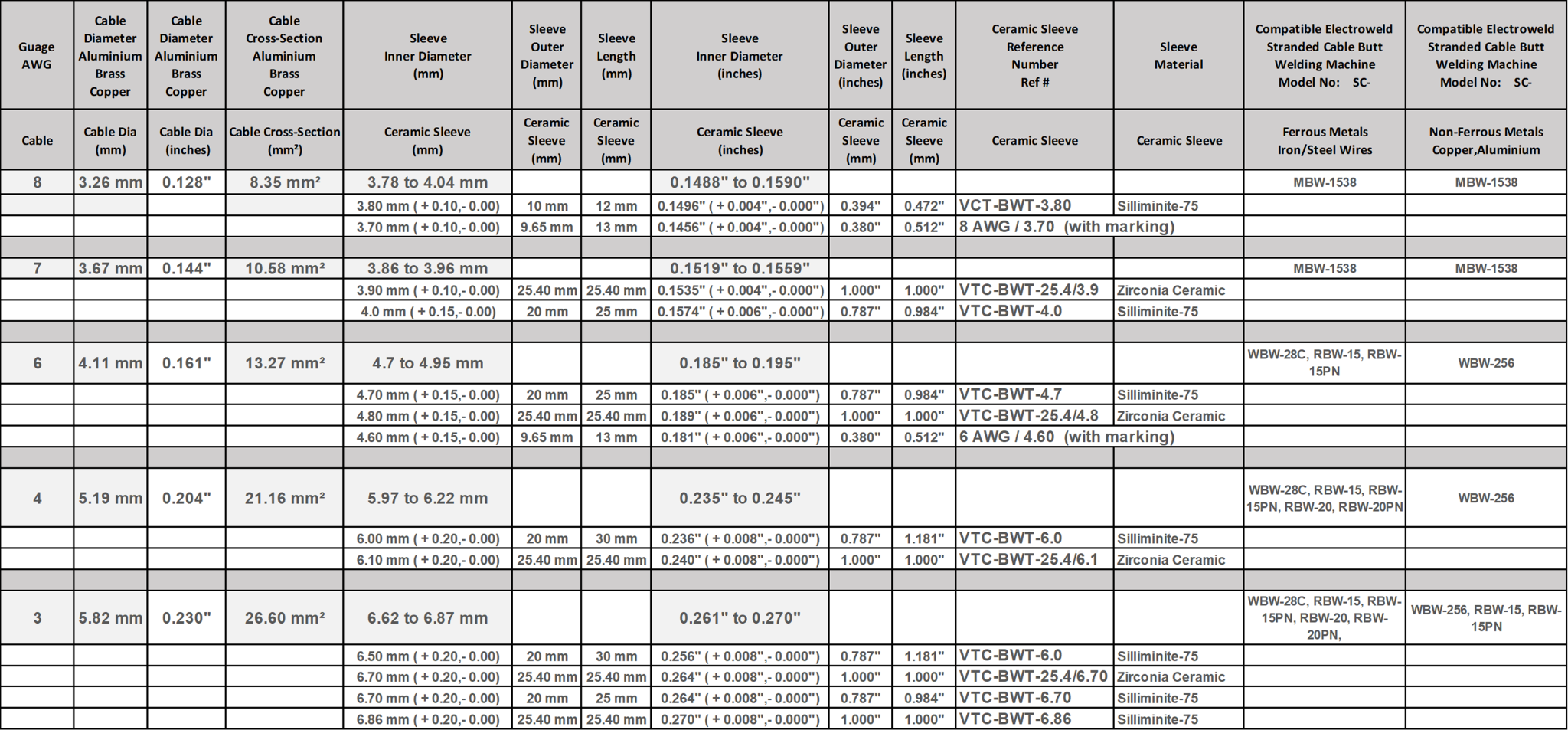
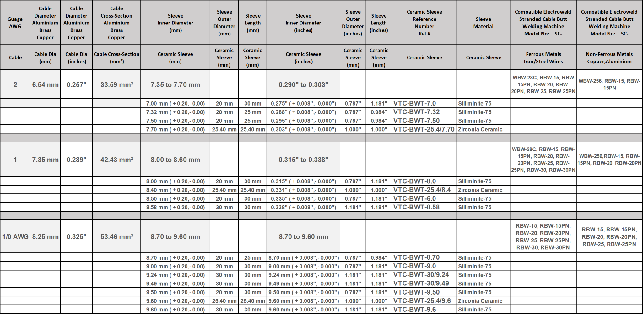
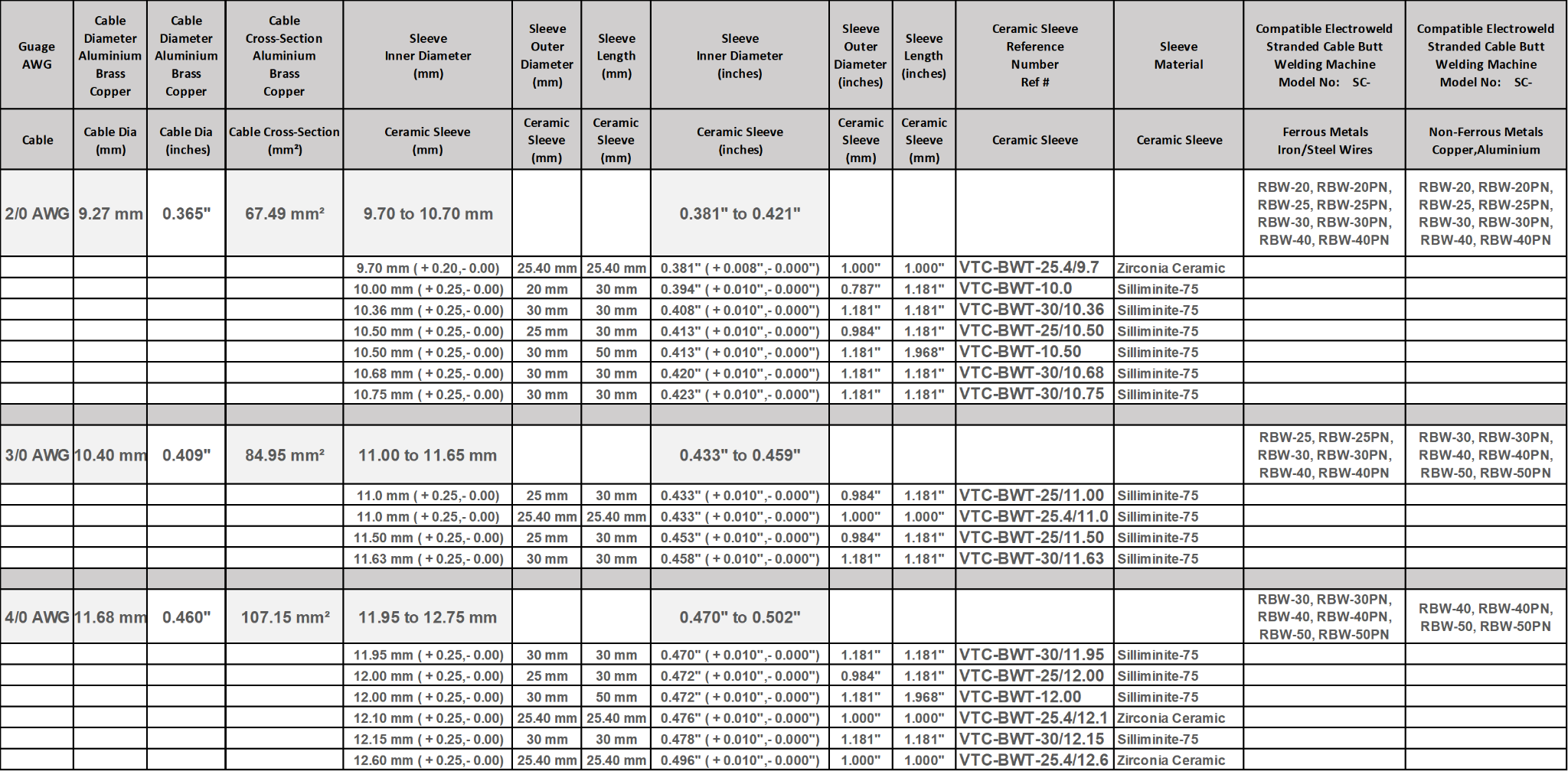
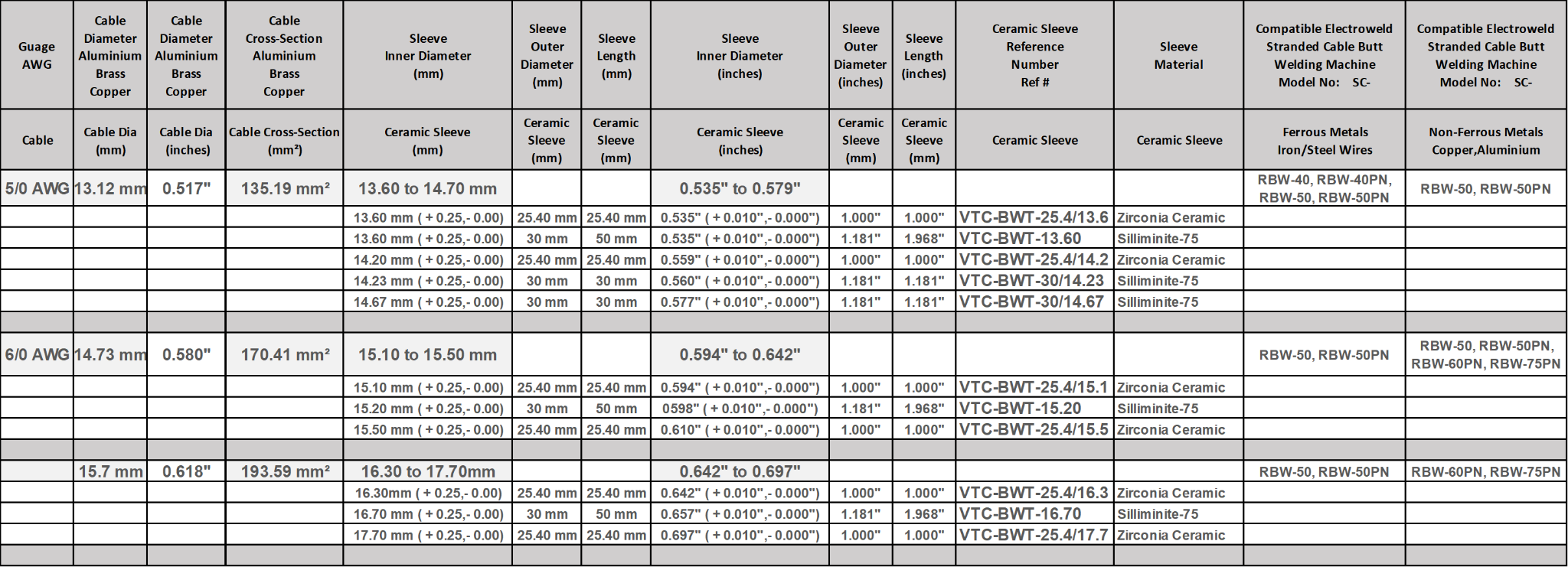
Note 1: Sleeve Inner Diameter Size Selection - Clearance between the sleeve and the conductor :
The conductor must slip in the sleeve but with a little friction to be well driven. If the clearance is too large, the axial rigidity of the strand is reduced and the wires begin to fold in the sleeve. The sleeve size must be considered as one would consider the size of a welding die. It must not stop the conductor from being introduced, but some friction needs to exist.
Additionally, the choice of a good cutter is an important step towards a successful weld. If we advise our users to do not over-strand the conductor after cutting, it is also for this reason. As the manual over-stranding is never regular, it changes not only the quality of sliding in the sleeve, but also the clearance and all the other parameters. Furthermore, another negative consequence of a larger diameter weld is the risk of being broken or drawn when it later goes through the insulation head.
Note 2: Using Right Tool for Cutting Stranded Conductor before introduction into the Ceramic Sleeve for Butt Welding :
The users often cut the conductors with scissors. Even if it is difficult to see, this increases the conductors length and let a flat burr outside the strand. Furthermore, the conductor un-strands easily and the user tries to over-strand it to keep it again rigid. As a result, he must then use a sleeve larger than necessary and this increases the clearance between the sleeve and the conductor. Another negative consequence of this over-stranding is the lay-length decrease which decreases the flowing of the melted metal between the wires. The operator must then increase the upset to compensate for the larger clearance but cannot increase the pressure because the conductor is less well driven in the sleeve during the fusion. As the welding is not satisfactory, the operator then requires longer sleeves, hoping to correct the problem. The weld then becomes longer and breaks easily after several folding in the accumulator further down the line.
In fact, a good driving in the sleeve requires as little as possible clearance between the sleeve and the conductor.
Following are some examples:
| cross sections |
clearance |
| 0.25 to 0.35 mm² |
0.03 to 0.05 mm |
| 1.5 to 4 mm² |
0.5 to 0.7 mm |
Note 3: Slipping the conductor in the sleeve :
We also suggest that the operator creates a small cone at the inlet of the sleeve to ease the strand introduction, and avoid any irregular over-stranding.
Note 4: Clamping of the conductor in the jaws :
When the conductor folds during the fusion, the reason is often a bad clamping in the jaws. When the pressure is applied, badly clamped conductors slice in the jaws and the weld turns around those ones which are correctly clamped. Theoretically, the best shape for the jaws is a circular groove but practically, we advice to use 'U' grooves because the setting and the clamping is more reliable.
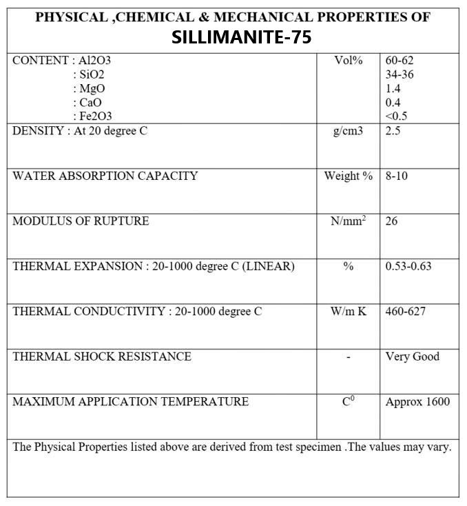
Specifications for Sillimanite used for making the Ceramic Sleeves :
Note: These Ceramic Sleeves are made with Sillimanite and other minerals. They mainly consists of Al2O3 and SiO2. Their physical and chemical properties are better than high grade Alumina Ceramics. Their max use temperature is 1600 ℃.
Note: MINIMUM ORDER QUANTITY (MOQ) FOR CERAMIC SLEEVES IN ANY PARTICULAR DIMENSION- 1000 Qty.
Please contact sales@electroweld.com for sample requests, price quotes or purchase orders for your required applications and quantities
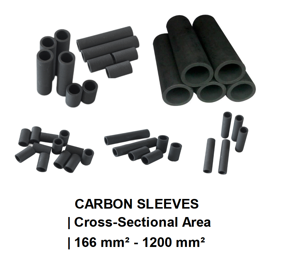
Electroweld Carbon Sleeves for Butt Welding Stranded Cable Cross-Sections : 166 mm² - 1200 mm²
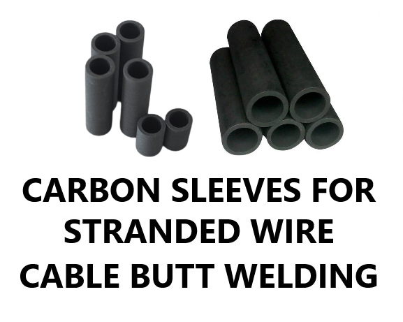
Applications: Electroweld Carbon Sleeves are designed for butt welding of stranded conductors. Example: For enabling continuous wire drawing manufacturing operations, the two ends of the stranded conductor to be welded are inserted into the Carbon Sleeve openings on each end, such that they meet in the middle of the tube. This assembly of the stranded cables and carbon sleeve is then clamped into the jaws of the matching Electroweld Butt Welding machine. When the butt welding process is initiated, the carbon sleeve act as crucible and the ends of the stranded conductors inside the sleeve fuse to form a burr free and pore free weld. The carbon sleeve is then broken with a hammer or mallet revealing the butt welded stranded cable which can then be processed upstream, ensuring continuous operations of the wire drawing manufacturing process.
Note: The Welding Jaw Clamping mechanism on Electroweld Butt Welding Machines is either Hand Operated, Foot Operated or Pneumatic Cylinder Operated, depending on the stranded conductor being welded and the corresponding matching machine rating. Regarding Upset Pressure mechanism in Electroweld Butt Welding Machines- For smaller cross-section stranded conductors, the butt welding upset pressure is applied via spring tension and for larger cross-section stranded conductors, the butt welding upset pressure is applied via pneumatic cylinders. Additionally the clamping pressure should be approximately twice the upset butt welding pressure to avoid slippage and turning of the stranded conductors inside the sleeve during butt welding.
Unique Characteristics of Graphite Sleeves for Butt Welding Application:
1. High electrical conductivity.
2. High thermal conductivity.
3. High thermal shock resistance.
4. Low co-efficient of thermal expansion.
5. Low modulus of elasticity.
6. High strength at elevated temperatures.
7. Highly inert to chemical attack.
8. Easily and readily machinable.
9. Non-wettable by molten metals.
A new concept : Apart from being available in larger cross-sections, Carbon sleeves or Carbon Tubes can be used to prevent or reduce oxidation during butt welding of stranded conductors
Advantages of this process: The Carbon Sleeve has a great characteristic: when it is heated at 300°C, it begins to produce a chemical reducing gas, the carbon monoxide gas, which avoids oxidation (in the case of aluminum) and even reduces it (in the case of copper).
Drawbacks of Glass or Ceramic Sleeves for Stranded Cable Butt Welding: The traditional processes of Butt welding Stranded Conductors, use a glass or ceramic tube to contain the melted metal but the drawback of these products is their inefficiency against the oxidation. This, in turn, requires to quickly fuse the butts, in order to avoid an excess of oxides, and in particular in stranded conductor which present, contrary to single conductor wires, a much larger area susceptible to oxidation. Furthermore, if the density of the current in the cross-section of a single wire is almost uniform, it is not the case for a multi-strand cable where the supply is applied only on the external layer. The inner layers current intensity is much lower because the electrical resistance between the layers. The more the layers, the worse the repartition of the current. For this reason, all the processes give similar results with small sections welding, but the significant differences appear with larger cross-sections where the impact of using Carbon Sleeves is more visible.
Methodology of Carbon Sleeves providing a reducing atmosphere during Stranded Cable Butt Welding: :
1. At the temperature reached during the butt welding operation, some carbon reacts with the air : 2 C + O2 = 2 CO
2. The carbon monoxide thus produced prevents the formation of alumina (Al2O3) by reacting with the oxygen BEFORE the aluminum.
3. With copper, the Carbon Sleeve will even reduce any possible copper oxide : CO + CuO = CO2 + Cu
This characteristic of the Carbon Sleeves is very useful in reducing oxidation of the welded joint during butt welding non-ferrous metal conductors like Aluminum or Copper and improves the quality of the final weld.
Ordering and Lead Times for Delivery :
Note: MINIMUM ORDER QUANTITY (MOQ) FOR CARBON SLEEVES IN ANY PARTICULAR DIMENSION- 100 Qty.
Minimum 4-5 Weeks Lead time for Delivery of MOQ. Samples could be made available earlier on request.
Please contact sales@electroweld.com for sample requests, price quotes or purchase orders for your required applications and quantities
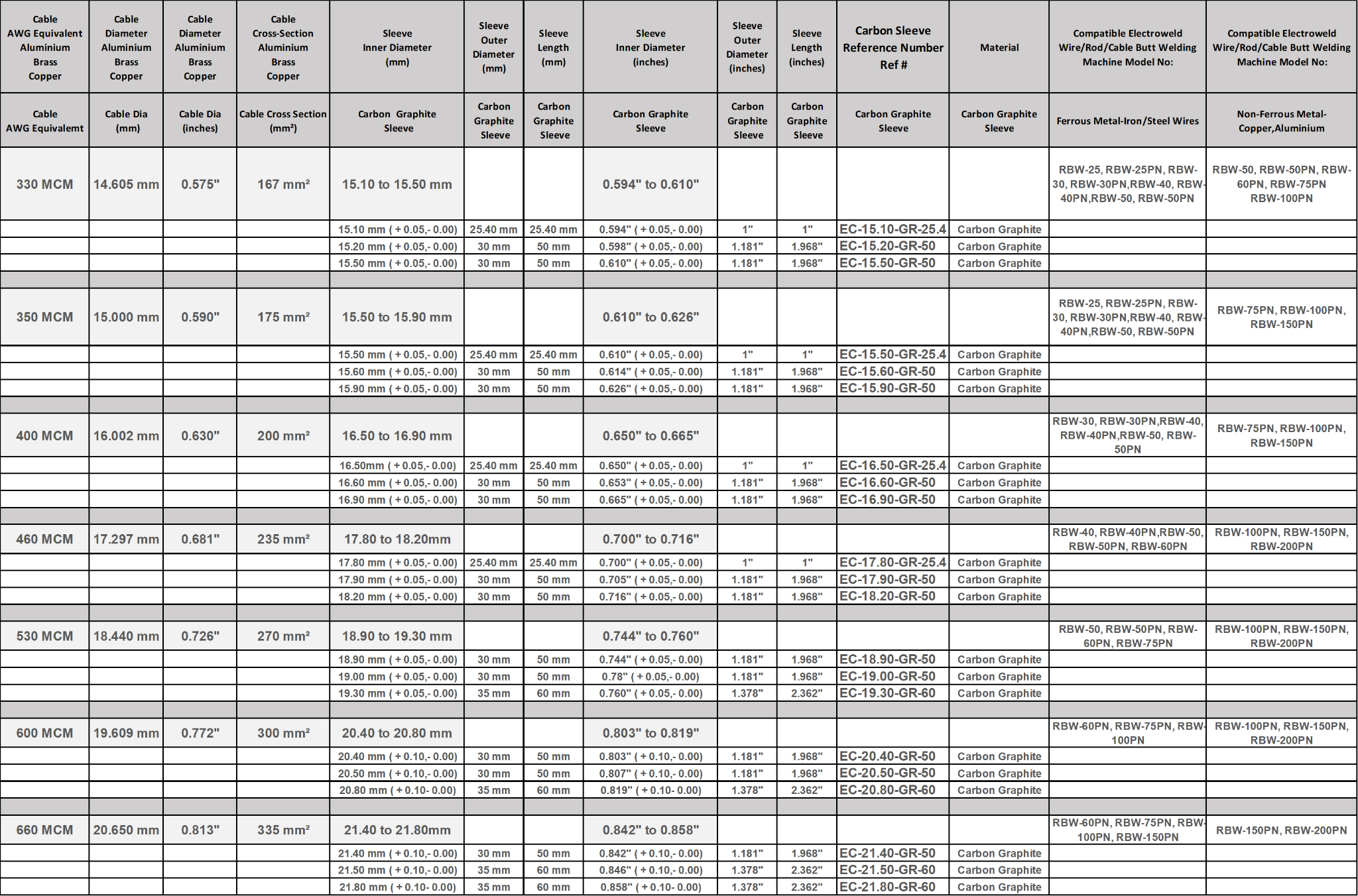
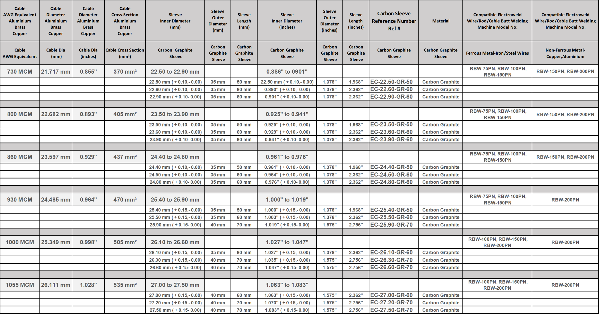
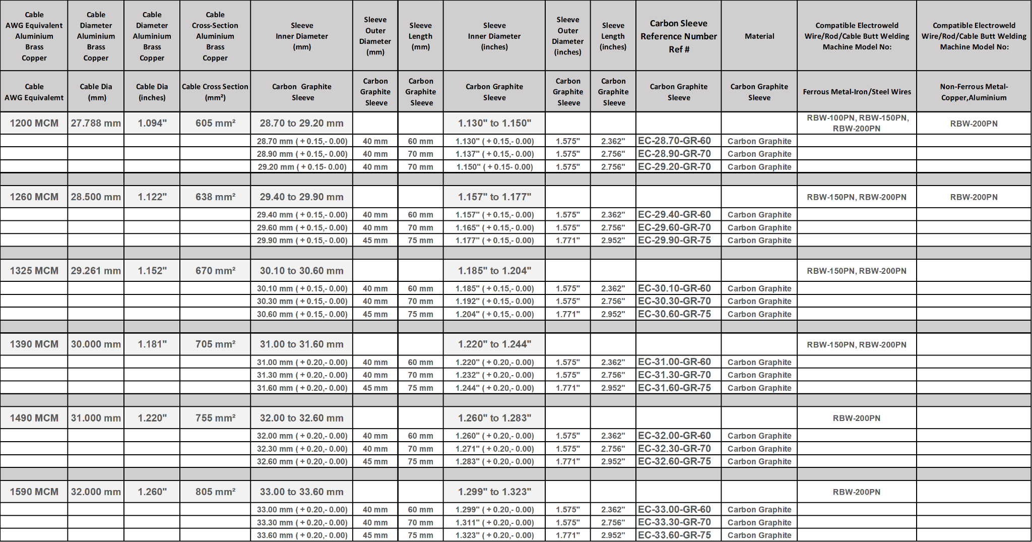
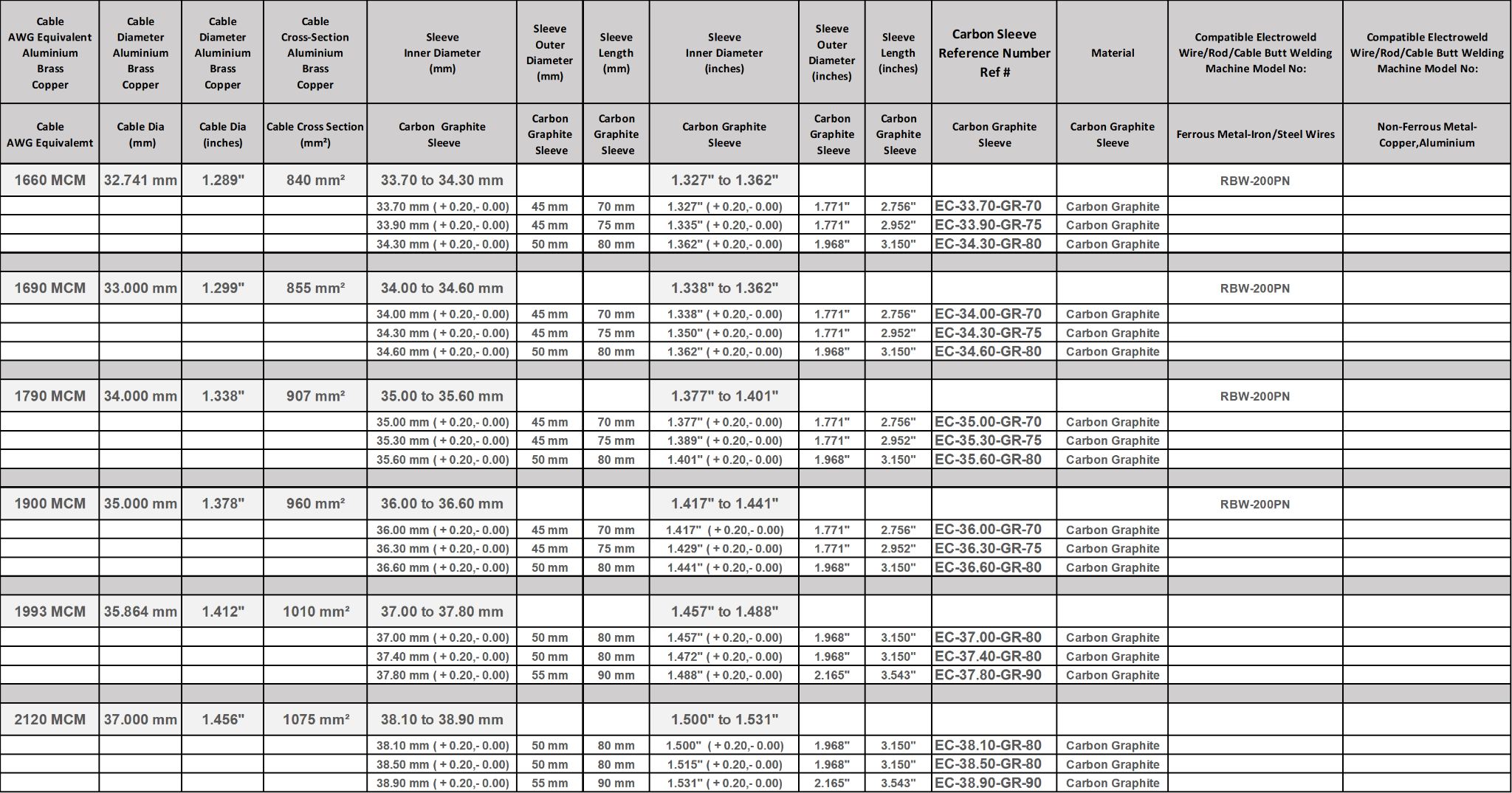
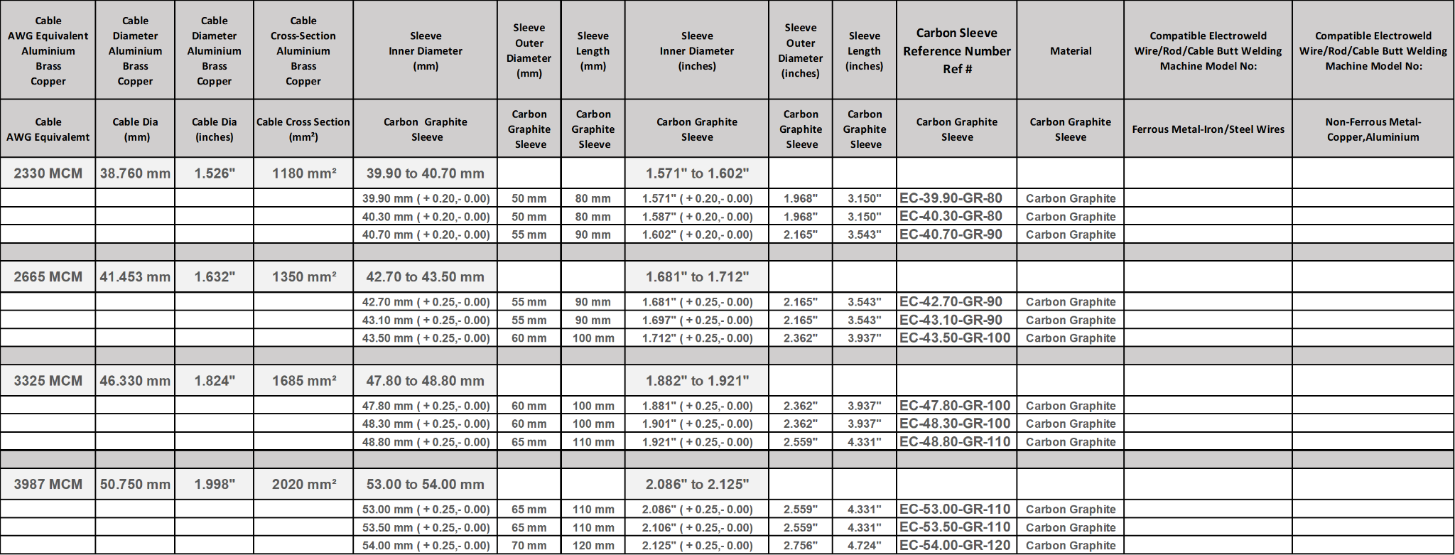
Specifications Table and Guide for Matching Various Carbon Sleeve Sizes to Specific Stranded Conductor Cross-Sections for Butt Welding Application :
Note 1: Sleeve Inner Diameter Size Selection - Clearance between the sleeve and the conductor :
The conductor must slip in the sleeve but with a little friction to be well driven. If the clearance is too large, the axial rigidity of the strand is reduced and the wires begin to fold in the sleeve. The sleeve size must be considered as one would consider the size of a welding die. It must not stop the conductor from being introduced, but some friction needs to exist.
Additionally, the choice of a good cutter is an important step towards a successful weld. If we advise our users to do not over-strand the conductor after cutting, it is also for this reason. As the manual over-stranding is never regular, it changes not only the quality of sliding in the sleeve, but also the clearance and all the other parameters. Furthermore, another negative consequence of a larger diameter weld is the risk of being broken or drawn when it later goes through the insulation head.
Note 2: Using Right Tool for Cutting Stranded Conductor before introduction into the Carbon Sleeve for Butt Welding :
The users often cut the conductors with scissors. Even if it is difficult to see, this increases the conductors length and let a flat burr outside the strand. Furthermore, the conductor un-strands easily and the user tries to over-strand it to keep it again rigid. As a result, he must then use a sleeve larger than necessary and this increases the clearance between the sleeve and the conductor. Another negative consequence of this over-stranding is the lay-length decrease which decreases the flowing of the melted metal between the wires. The operator must then increase the upset to compensate for the larger clearance but cannot increase the pressure because the conductor is less well driven in the sleeve during the fusion. As the welding is not satisfactory, the operator then requires longer sleeves, hoping to correct the problem. The weld then becomes longer and breaks easily after several folding in the accumulator further down the line.
In fact, a good driving in the sleeve requires as little as possible clearance between the sleeve and the conductor.
Following are some examples:
| cross sections |
clearance |
| 0.25 to 0.35 mm² |
0.03 to 0.05 mm |
| 1.5 to 4 mm² |
0.5 to 0.7 mm |
Note 3: Slipping the conductor in the sleeve :
We also suggest that the operator creates a small cone at the inlet of the sleeve to ease the strand introduction, and avoid any irregular over-stranding.
Note 4: Clamping of the conductor in the jaws :
When the conductor folds during the fusion, the reason is often a bad clamping in the jaws. When the pressure is applied, badly clamped conductors slice in the jaws and the weld turns around those ones which are correctly clamped. Theoretically, the best shape for the jaws is a circular groove but practically, we advice to use 'U' grooves because the setting and the clamping is more reliable.
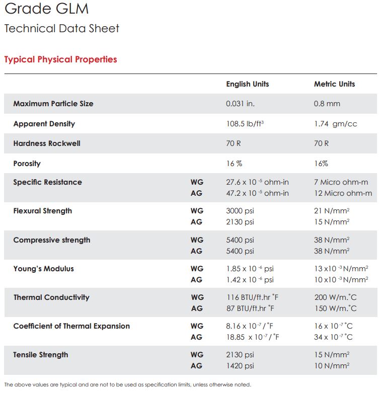
Specifications For GLM Graphite used for making the Extruded Carbon Graphite Sleeves :
Note: GLM used for making Carbon Sleeves–It is characterized by higher density, higher strength and lower porosity. It has a finer structure and can be machined to a fine finish.
Note: MINIMUM ORDER QUANTITY (MOQ) FOR CARBON SLEEVES IN ANY PARTICULAR DIMENSION- 100 Qty.
Please contact sales@electroweld.com for sample requests, price quotes or purchase orders for your required applications and quantities
